A 0402 capacitor that reads correctly on a bench meter can still produce a misleading result when measured through long leads, worn clips, or an uncorrected fixture. That gap between a displayed value and a defensible measurement is where electronic test equipment proves its value. For engineering, production, repair, and quality teams, the question is not whether an instrument powers on. It is whether its result supports a reliable disposition decision.
A capable measurement system must do more than identify resistance, capacitance, or inductance. It must control the electrical conditions around the device under test, resolve the relevant value range, repeat measurements consistently, and fit the actual workflow. Those requirements change significantly when moving from through-hole parts to fine-pitch SMD inventory, from general troubleshooting to incoming inspection, or from a lab bench to field service.
What Electronic Test Equipment Must Actually Deliver
Instrument selection often starts with a familiar specification: basic accuracy. Accuracy matters, but it is only one part of useful measurement performance. A stated 0.1% basic accuracy can be meaningful only when the test frequency, test voltage, equivalent circuit model, calibration state, connection method, and component value all suit the application.
Consider a ceramic capacitor below 1 pF. At that level, fixture capacitance, cable motion, probe geometry, humidity, and operator handling can overwhelm the part being measured. Similarly, inductors in the low-nanohenry range are strongly affected by lead length and loop area. An instrument with a broad nominal range is not automatically the right instrument unless its connection method and correction functions preserve resolution at the low end.
For practical component evaluation, electronic test equipment should provide four outcomes:
- A value measured under known, appropriate test conditions
- Repeatable results across operators and test stations
- Clear identification of opens, shorts, leakage, drift, or out-of-tolerance parts
- A measurement record that can support troubleshooting, inspection, or process review
The best balance depends on the task. A production engineer screening reels of passive components may prioritize speed and repeatability. A repair technician diagnosing a populated board may need direct contact with installed parts and fast automatic identification. A laboratory team may require data logging, calibration documentation, and controlled measurement at multiple frequencies.
Start With the Component and Failure Mode
The most efficient test workflow begins with a precise question. “Measure this component” is not precise enough. The task may be to verify a nominal value, separate good and suspect inventory, identify a component type, characterize frequency-dependent behavior, or locate degradation after thermal or electrical stress.
Passive component verification
Resistors are straightforward until contact resistance becomes comparable to the value being measured. Low-ohm measurements require proper Kelvin techniques to separate test-current paths from voltage sensing. Without that separation, probe pressure and connector resistance can become part of the result.
Capacitors require more context. Capacitance at 1 kHz may be useful for a general-purpose ceramic part, but an electrolytic capacitor may also need ESR evaluation at a relevant frequency. A capacitor can retain a nominal capacitance value while exhibiting elevated ESR that causes ripple, startup, or transient-response failures in circuit operation.
Inductors introduce another layer of dependency. Inductance values vary with frequency, DC bias, core material, and test level. Small inductors can be particularly difficult because parasitic inductance from the test connection can equal or exceed the device value. A short, direct-contact connection is usually more valuable than a convenient but electrically long clip lead.
In-circuit troubleshooting
In-circuit measurement is never entirely isolated measurement. Parallel paths, semiconductor junctions, charged capacitors, and active circuitry can alter the result. The correct approach is to treat an in-circuit reading as diagnostic evidence, then confirm by lifting one lead or removing the component when the circuit topology makes isolation necessary.
That does not make in-circuit testing less useful. It makes speed more valuable. A technician who can quickly compare suspect locations against known-good channels, neighboring circuits, or expected signatures can narrow a fault before committing to rework. Direct-contact probes and automatic component identification reduce handling time where traditional leads are too large or too slow for dense boards.
Incoming inspection and counterfeit screening
Incoming inspection is often a comparison problem rather than a single absolute-value problem. A reel labeled with one value but containing mixed components may show inconsistent capacitance, resistance, inductance, or dissipation behavior. Counterfeit or substituted parts can also produce a nominal DC value while failing at the test frequency or voltage that reflects their intended use.
For this work, repeatability matters as much as resolution. The inspection procedure should define the component orientation, contact method, test frequency, acceptance limits, and calibration status. If two inspectors cannot reproduce the same reading within a justified tolerance, the process is not yet ready for reliable pass/fail decisions.
Frequency and Parasitics Are Not Secondary Details
Every component is frequency dependent to some degree. A real capacitor includes ESR and inductance. A real inductor includes winding resistance and distributed capacitance. A resistor can become inductive or capacitive at sufficiently high frequencies. The instrument must therefore be selected around the behavior that matters in the circuit, not only around the printed nominal value.
Test frequency is especially consequential for impedance measurements. Higher frequencies can reveal characteristics that remain hidden at low frequency, but they also demand better fixturing and more disciplined handling. A 250 kHz test capability can be valuable for evaluating small passive parts and high-frequency behavior, yet it does not eliminate the need to select the right equivalent model and minimize the test path.
Parasitic control begins with physical geometry. Long leads add inductance. Open probe jaws and fixture surfaces add capacitance. Oxidized contacts add resistance and instability. The smallest measurable value is therefore not defined by the instrument display alone. It is defined by the complete measurement setup.
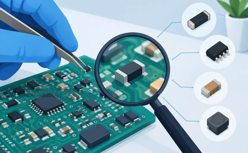
This is why tweezer-form instruments have a distinct place in professional workflows. By bringing two controlled contacts directly to an SMD device, they reduce loop area, shorten the electrical path, and eliminate the setup burden of clips or cables. For tiny components, that connection method can be the difference between a stable reading and a number that drifts with every hand movement.
Calibration Turns a Reading Into Evidence
Calibration is often treated as an administrative requirement. In reality, it is part of the measurement system. A calibration interval, documented standards, correction procedures, and traceability establish whether an instrument can be relied upon within its stated uncertainty.
For organizations working under formal quality systems, calibration documentation supports audits and process control. For individual engineers and repair specialists, it provides a different but equally practical benefit: confidence that an unexpected measurement is more likely to indicate the device under test than an instrument that has drifted out of specification.
Users should also distinguish between calibration and daily verification. Calibration confirms performance against traceable standards at defined intervals. Daily verification checks whether the instrument, probes, and operator setup are behaving as expected before critical work begins. A calibrated meter connected through a damaged Kelvin connector is not a calibrated measurement system.
A disciplined verification routine should include known-value standards near the range of interest, inspection of probe contacts, battery or power checks, and open/short compensation where the instrument supports it. For low capacitance and low inductance work, these steps are not optional refinements. They are part of acquiring valid data.
Portable Does Not Need to Mean Compromised
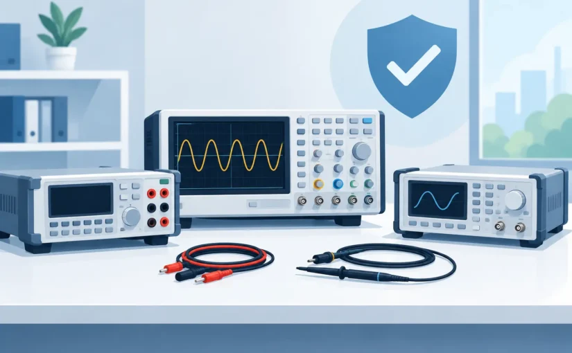
Traditional bench instruments remain appropriate for many applications, particularly automated test, multi-terminal measurements, and controlled laboratory characterization. Their size, interface options, and fixture compatibility can justify the bench footprint.
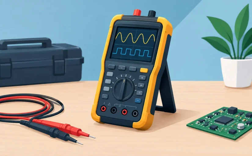
But portability is no longer synonymous with approximate measurement. Modern handheld LCR and ESR instruments can provide bench-grade capability for work that happens at a production line, a rework station, a customer site, or inside a lab where the component is not conveniently located beside a bench analyzer. The advantage is not merely convenience. It is faster decision-making at the point where the fault, component, or assembly is present.
LCR-Reader instruments illustrate the practical value of this approach: direct-contact measurement, automatic component identification, high test frequencies, and precision capability in a handheld format. For many SMD workflows, eliminating the transfer from board or parts tray to a remote test fixture removes more delay than any incremental improvement in display speed.
Bluetooth-enabled data recording adds another layer of utility when results must be retained rather than observed once. Logging supports trend analysis, documentation of inspection lots, comparison of pre- and post-rework values, and remote review. It is not required for every repair bench, but it becomes highly valuable when a measurement needs to be communicated, repeated, or audited.
Build the Measurement Method Around the Decision
The correct instrument is the one that reduces uncertainty in the decision that follows. If a technician needs to identify a failed 0201 capacitor on a board, direct-contact access and low-capacitance resolution may matter more than a large bench display. If a quality department is accepting components against a customer specification, traceable calibration, defined test conditions, and recorded results may take priority. If a design team is investigating switching noise, frequency selection and equivalent circuit modeling become central.
That distinction prevents two costly mistakes: buying more capability than the workflow can use, and buying a general-purpose meter for a measurement that requires controlled parasitics and defined impedance conditions. Electronic test equipment earns its place when it makes the next engineering decision faster, more repeatable, and easier to defend.
The final check is simple: measure a known reference, measure the actual component under realistic conditions, and ask whether the result would hold up when a production line, customer return, or design review depends on it.